
Skip to content
Show3D
  • Community
  • Pricing
Search scenes
Create
OverviewDocumentationTutorials & coursesSearch Learn
  • Overview
  • Get started with Show3D
  • Modeling tools
    • Modeling examples
  • Materials & textures
  • Agent modeling
    • Connect Codex
  • Asset generation

In this topic

  • Extrude
  • Bevel
  • Select components
  • Select a loop
  • Extrude a vertex
  • Extrude an edge
  • Inset a region
  • Inset individual faces
  • Bevel a vertex
  • Loop cut
  • Knife cut
  • Connect vertices
  • Subdivide a mesh
  • Triangulate
  • Triangles to quads
Browse documentation
  • Overview
  • Get started with Show3D
  • Modeling tools
    • Modeling examples
  • Materials & textures
  • Agent modeling
    • Connect Codex
  • Asset generation

In this topic

  • Extrude
  • Bevel
  • Select components
  • Select a loop
  • Extrude a vertex
  • Extrude an edge
  • Inset a region
  • Inset individual faces
  • Bevel a vertex
  • Loop cut
  • Knife cut
  • Connect vertices
  • Subdivide a mesh
  • Triangulate
  • Triangles to quads

Learn

Learn overviewDocumentationTutorials & coursesConnect Codex
XiaohongshuDouyinBilibili

Copyright © 2023 - 2026 Show3D Technology Limited. All rights reserved.

Terms of UsePrivacy Policy
Modeling tools
  1. Learn
  2. Documentation
  3. Modeling tools
  4. Extrude a vertex

Extrude a vertex

Extend a selected vertex and connect it to the new vertex with an edge. This wire edit creates an edge rather than a face.

Before you start

Enter mesh edit mode and use Vertex Select. Select a vertex at the end of a wire or at the intended start of an extension. A vertex extrusion creates connected edges; it does not by itself make a filled surface.

Use the operation

Extend a wire path one segment at a time.

  1. Select the endpoint and choose Extrude in the vertex context menu.
  2. Move the newly created vertex away from the source to define the next segment.
  3. Confirm, then repeat from the new endpoint when another segment is needed.
  4. Inspect the path from another view before filling or connecting it to other geometry.

Controls and choices

ControlsWhat changes
Vertex selectionEach selected vertex can contribute to the extension. Select one endpoint for a single new wire segment.
OffsetDetermines the new edge's length and direction. A zero-length segment is not a useful extension.

See what changes

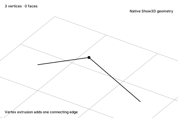
Before

Extrude a vertex: A selected wire vertex

A selected wire vertex

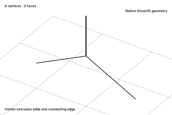
After

Extrude a vertex: A new connected vertex

A new connected vertex

Concept illustration. The diagrams explain the operation. Your result depends on the starting geometry and settings.

Check the result

Confirm a new edge connects the original and new vertex. Multiple selected endpoints can create more geometry than expected. An open wire has no surface to shade; use a suitable closed boundary and Fill when you need a face.

Related operations

Extrude an edgeFill a boundaryConnect vertices

Practice in Show3D

Open the editor and follow the steps with your own scene.
Start modelingModeling essentials

On this page

Before you startUse the operationControls and choicesSee what changesCheck the resultRelated operations