Skip to content
Show3D
  • Community
  • Pricing
Search scenes
Create
OverviewDocumentationTutorials & coursesSearch Learn
  • Overview
  • Get started with Show3D
  • Modeling tools
    • Modeling examples
  • Materials & textures
  • Agent modeling
    • Connect Codex
  • Asset generation
Browse documentation
  • Overview
  • Get started with Show3D
  • Modeling tools
    • Modeling examples
  • Materials & textures
  • Agent modeling
    • Connect Codex
  • Asset generation

Learn

Learn overviewDocumentationTutorials & coursesConnect Codex
XiaohongshuDouyinBilibili

Copyright © 2023 - 2026 Show3D Technology Limited. All rights reserved.

Terms of UsePrivacy Policy
Modeling tools
  1. Learn
  2. Documentation
  3. Modeling tools
  4. Modeling examples

Modeling examples

The diagrams explain the operation. Your result depends on the starting geometry and settings.

Interactive examples
Create & arrangeShape & topologyConnect & repairModifiers & solidsCurves & profilesSculpt & surface

Create & arrange

Add a primitive

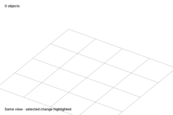
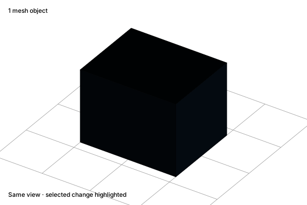
Start with a basic mesh. Its vertices, edges, and faces can be selected and developed into a more detailed form.

Before

Add a primitive: An empty work area

An empty work area

After

Add a primitive: An editable starting shape

An editable starting shape

Concept illustration. The diagrams explain the operation. Your result depends on the starting geometry and settings.
Before · SVGAfter · SVG
ReferenceExplore interactive example

Move

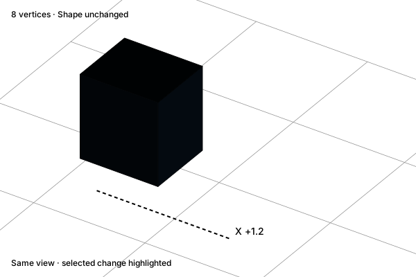
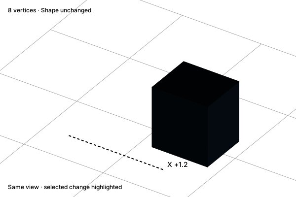
Translate the object along an axis. Its shape, dimensions, and topology stay the same.

Before

Move: Original position

Original position

After

Move: Moved on one axis

Moved on one axis

Concept illustration. The diagrams explain the operation. Your result depends on the starting geometry and settings.
Before · SVGAfter · SVG
ReferenceExplore interactive example

Rotate

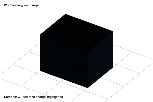
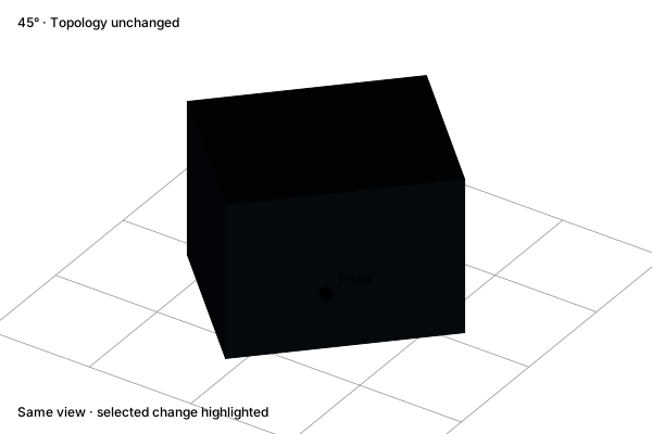
Rotate the object about its pivot. Vertex distances from that pivot are preserved.

Before

Rotate: Original orientation

Original orientation

After

Rotate: Turned about the pivot

Turned about the pivot

Concept illustration. The diagrams explain the operation. Your result depends on the starting geometry and settings.
Before · SVGAfter · SVG
ReferenceExplore interactive example

Scale

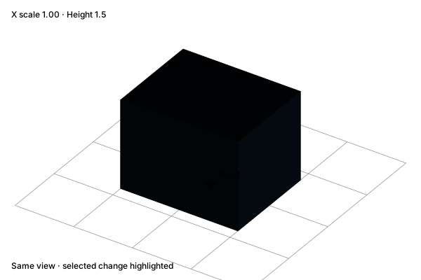
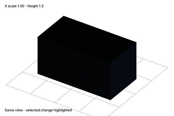
Change the object’s width while preserving its height. This example uses an axis constraint and a fixed pivot.

Before

Scale: Original proportions

Original proportions

After

Scale: Scaled on one axis

Scaled on one axis

Concept illustration. The diagrams explain the operation. Your result depends on the starting geometry and settings.
Before · SVGAfter · SVG
ReferenceExplore interactive example

Duplicate

Make a separate copy and move it beside the source. Duplicating does not connect their topology.

Before

Duplicate: One object

One object

After

Duplicate: Two independent objects

Two independent objects

Concept illustration. The diagrams explain the operation. Your result depends on the starting geometry and settings.
Before · SVGAfter · SVG
ReferenceExplore interactive example

Repeat in a line

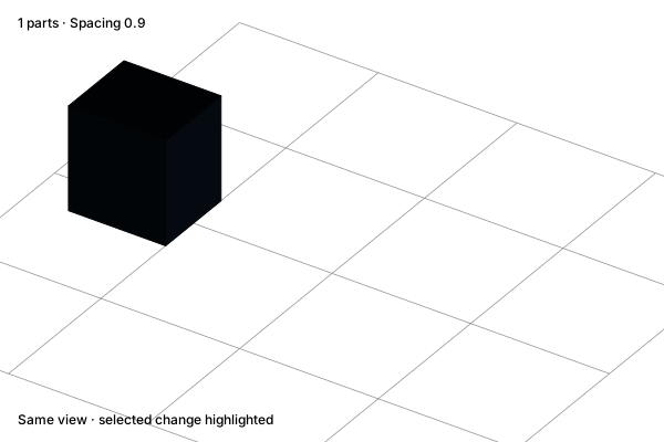
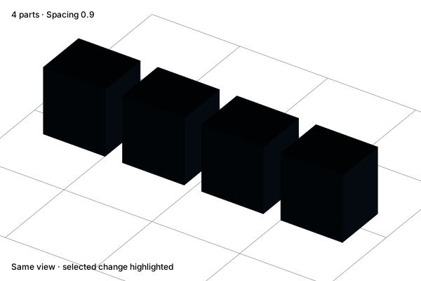
Arrange repeated parts at a consistent interval. Codex can include repetition in a scene plan.

Before

Repeat in a line: One source part

One source part

After

Repeat in a line: A row of repeated parts

A row of repeated parts

Concept illustration. The diagrams explain the operation. Your result depends on the starting geometry and settings.
Before · SVGAfter · SVG
ReferenceExplore interactive example

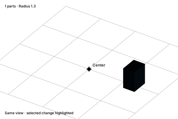
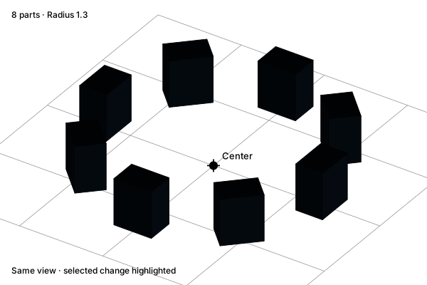
Repeat around a center

Distribute repeated parts around a shared center. The example keeps their radius and angular interval consistent.

Before

Repeat around a center: One source part

One source part

After

Repeat around a center: A radial arrangement

A radial arrangement

Concept illustration. The diagrams explain the operation. Your result depends on the starting geometry and settings.
Before · SVGAfter · SVG
ReferenceExplore interactive example

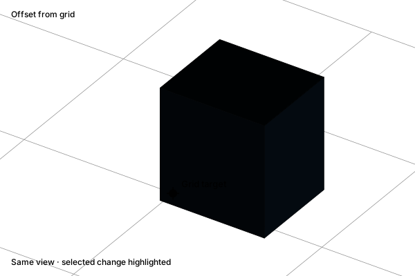
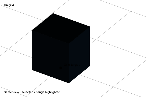
Snap to a grid

Use a grid target to place geometry precisely. Enabling snapping prepares a transform; it does not move an object by itself.

Before

Snap to a grid: An offset placement

An offset placement

After

Snap to a grid: Aligned to a grid point

Aligned to a grid point

Concept illustration. The diagrams explain the operation. Your result depends on the starting geometry and settings.
Before · SVGAfter · SVG
ReferenceExplore interactive example

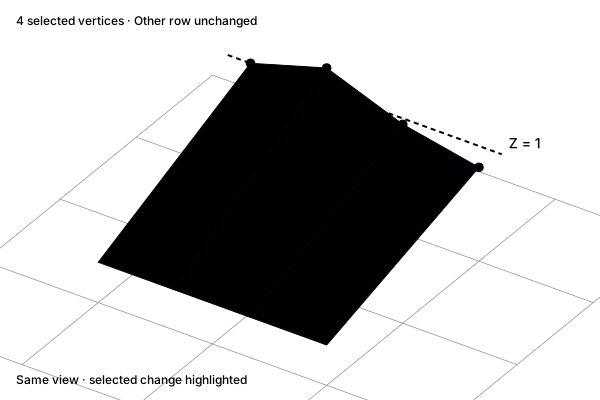
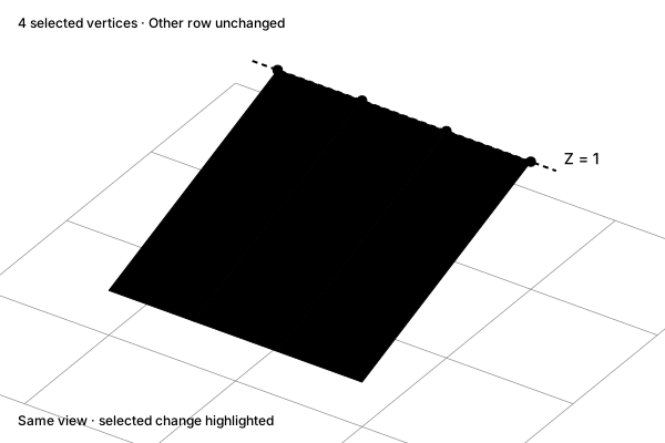
Align vertices

Move selected vertices onto the same world-axis coordinate. The other row remains fixed.

Before

Align vertices: Uneven vertex heights

Uneven vertex heights

After

Align vertices: A level edge row

A level edge row

Concept illustration. The diagrams explain the operation. Your result depends on the starting geometry and settings.
Before · SVGAfter · SVG
ReferenceExplore interactive example

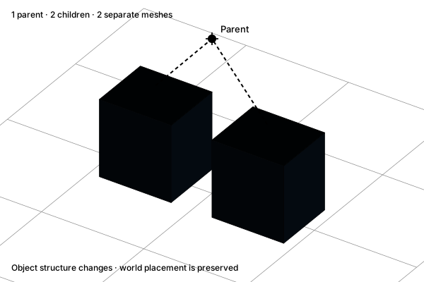
Group objects

Organize objects under a parent while preserving separate meshes. Moving the group can move the assembly together.

Before

Group objects: Two separate objects

Two separate objects

After

Group objects: One parent, two children

One parent, two children

Concept illustration. The diagrams explain the operation. Your result depends on the starting geometry and settings.
Before · SVGAfter · SVG
ReferenceExplore interactive example

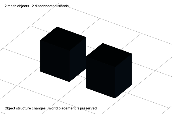
Join meshes

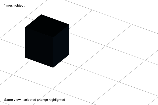
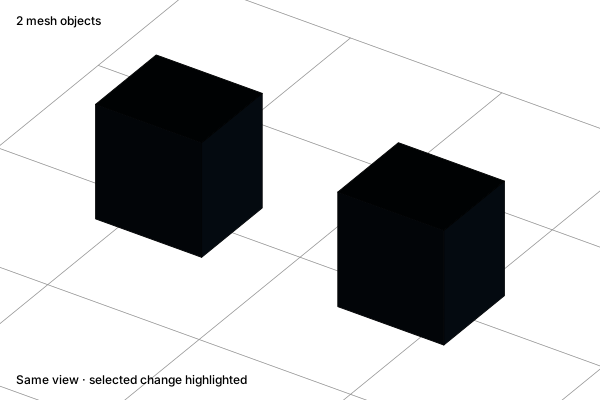
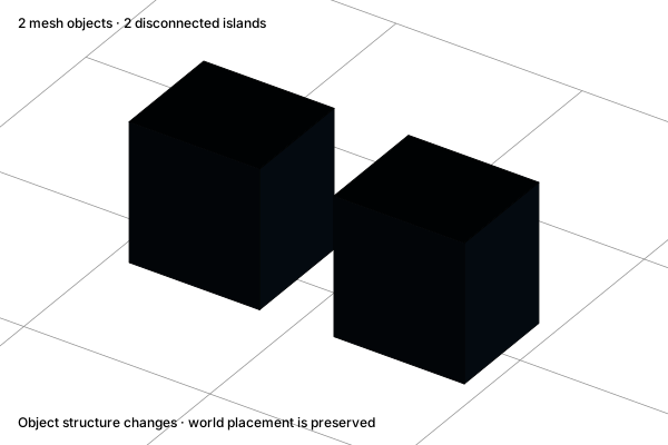
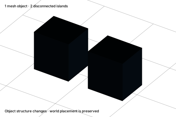
Combine mesh objects into one object. Separate islands can remain; joining does not remove overlapping volume like a boolean union.

Before

Join meshes: Two mesh objects

Two mesh objects

After

Join meshes: One mesh object

One mesh object

Concept illustration. The diagrams explain the operation. Your result depends on the starting geometry and settings.
Before · SVGAfter · SVG
ReferenceExplore interactive example

Set the origin

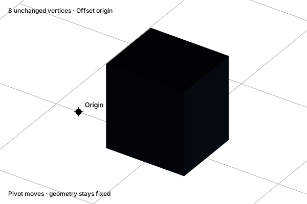
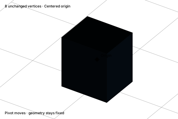
Move the object’s origin to its geometry center while preserving the world-space position of every vertex.

Before

Set the origin: An offset pivot

An offset pivot

After

Set the origin: Pivot at the geometry center

Pivot at the geometry center

Concept illustration. The diagrams explain the operation. Your result depends on the starting geometry and settings.
Before · SVGAfter · SVG
ReferenceExplore interactive example

Apply transforms

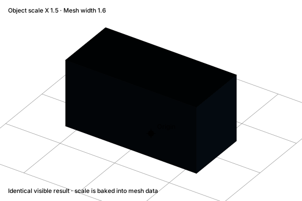
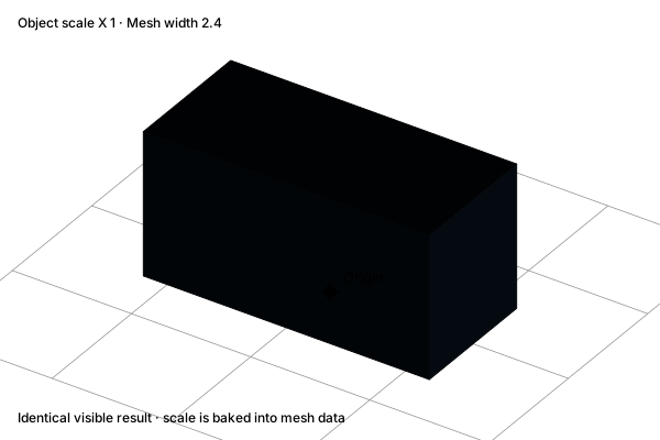
Bake scale into the mesh data and reset the object scale. The visible shape and world-space dimensions remain unchanged.

Before

Apply transforms: Scaled object transform

Scaled object transform

After

Apply transforms: Scale baked into the mesh

Scale baked into the mesh

Concept illustration. The diagrams explain the operation. Your result depends on the starting geometry and settings.
Before · SVGAfter · SVG
ReferenceExplore interactive example

Shape & topology

Extrude

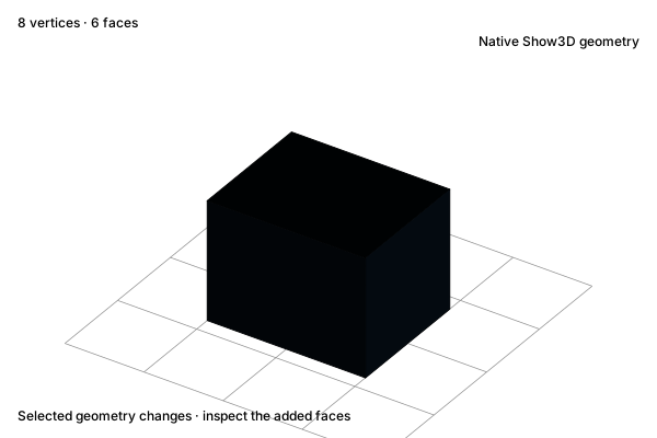
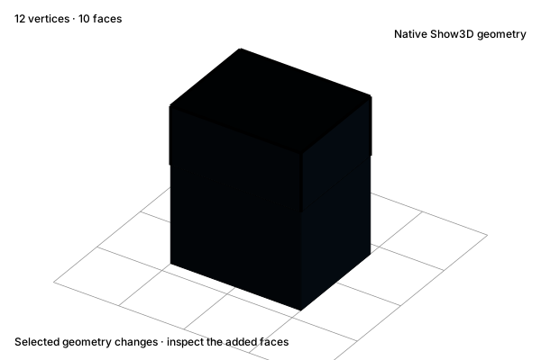
Move the selected face outward and connect it to the existing boundary with new side faces. The original base stays fixed.

Before

Extrude: Select a face

Select a face

After

Extrude: Extend the surface

Extend the surface

Concept illustration. The diagrams explain the operation. Your result depends on the starting geometry and settings.
Before · SVGAfter · SVG
ReferenceExplore interactive example

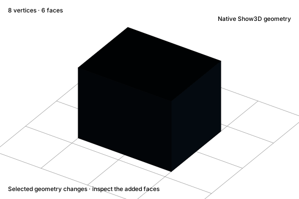
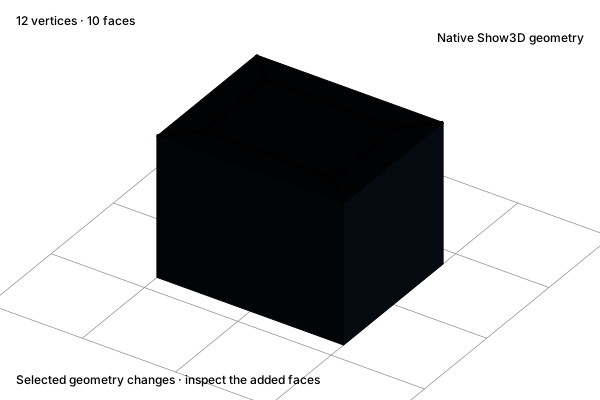
Bevel

Cut back the four vertical edges to create narrow faces. This single-segment bevel changes the geometry of each corner.

Before

Bevel: Sharp vertical edges

Sharp vertical edges

After

Bevel: Chamfered vertical edges

Chamfered vertical edges

Concept illustration. The diagrams explain the operation. Your result depends on the starting geometry and settings.
Before · SVGAfter · SVG
ReferenceExplore interactive example

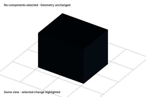
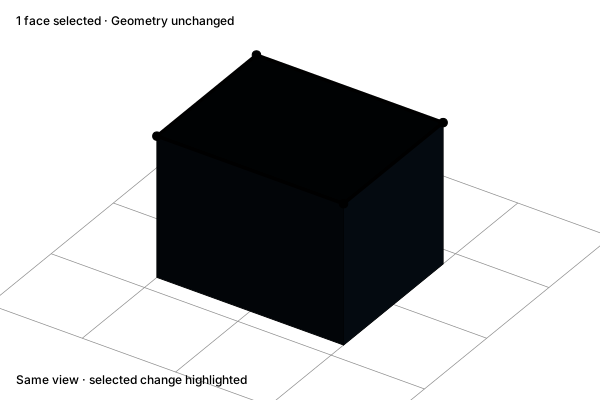
Select components

Choose vertices, edges, or faces to focus an edit. Selection alone changes no geometry.

Before

Select components: The whole mesh

The whole mesh

After

Select components: A selected face and boundary

A selected face and boundary

Concept illustration. The diagrams explain the operation. Your result depends on the starting geometry and settings.
Before · SVGAfter · SVG
ReferenceExplore interactive example

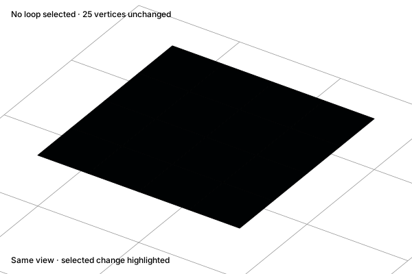
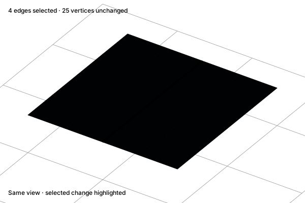
Select a loop

Follow a connected edge pattern to select a useful region. Edge loops and rings are different selection patterns.

Before

Select a loop: A connected quad grid

A connected quad grid

After

Select a loop: A selected edge loop

A selected edge loop

Concept illustration. The diagrams explain the operation. Your result depends on the starting geometry and settings.
Before · SVGAfter · SVG
ReferenceExplore interactive example

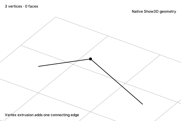
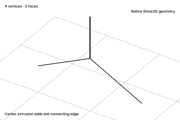
Extrude a vertex

Extend a selected vertex and connect it to the new vertex with an edge. This wire edit creates an edge rather than a face.

Before

Extrude a vertex: A selected wire vertex

A selected wire vertex

After

Extrude a vertex: A new connected vertex

A new connected vertex

Concept illustration. The diagrams explain the operation. Your result depends on the starting geometry and settings.
Before · SVGAfter · SVG
ReferenceExplore interactive example

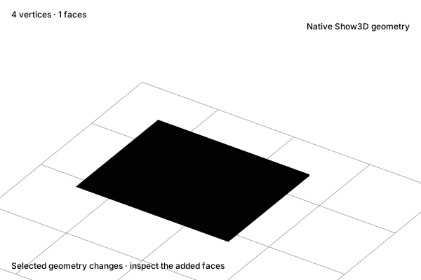
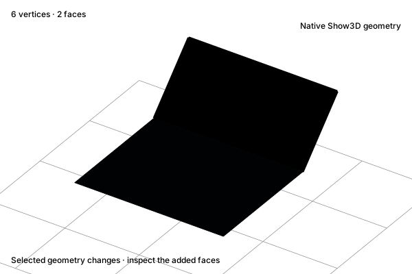
Extrude an edge

Extend an open boundary edge and create a connected face between the original and new edge.

Before

Extrude an edge: A boundary edge

A boundary edge

After

Extrude an edge: An extended strip

An extended strip

Concept illustration. The diagrams explain the operation. Your result depends on the starting geometry and settings.
Before · SVGAfter · SVG
ReferenceExplore interactive example

Inset a region

Create a border inside a face region. The outside boundary stays fixed, and the new inner face can be extruded next.

Before

Inset a region: A selected face

A selected face

After

Inset a region: An inner face and border

An inner face and border

Concept illustration. The diagrams explain the operation. Your result depends on the starting geometry and settings.
Before · SVGAfter · SVG
ReferenceExplore interactive example

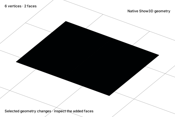
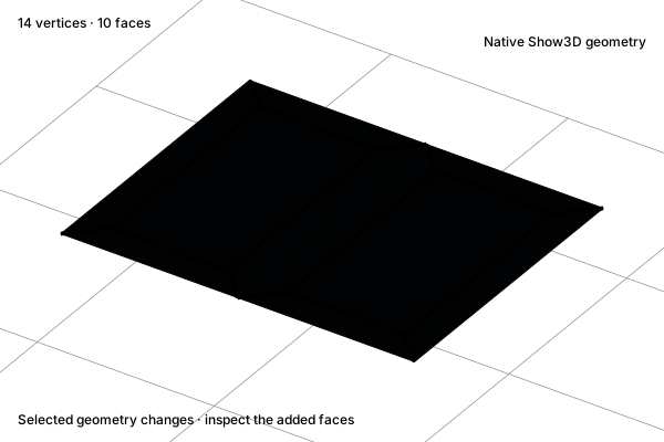
Inset individual faces

Give each selected face its own inset border. The separate borders distinguish this operation from a region inset.

Before

Inset individual faces: Adjacent faces

Adjacent faces

After

Inset individual faces: A border in each face

A border in each face

Concept illustration. The diagrams explain the operation. Your result depends on the starting geometry and settings.
Before · SVGAfter · SVG
ReferenceExplore interactive example

Bevel a vertex

Replace a selected corner with a small face and connecting edges. Other corners retain their original shape.

Before

Bevel a vertex: One sharp corner

One sharp corner

After

Bevel a vertex: A cut-off corner face

A cut-off corner face

Concept illustration. The diagrams explain the operation. Your result depends on the starting geometry and settings.
Before · SVGAfter · SVG
ReferenceExplore interactive example

Loop cut

Insert a connected edge loop through the quad faces. The surface shape stays fixed while topology gains another control row.

Before

Loop cut: An uncut quad strip

An uncut quad strip

After

Loop cut: A new continuous loop

A new continuous loop

Concept illustration. The diagrams explain the operation. Your result depends on the starting geometry and settings.
Before · SVGAfter · SVG
ReferenceExplore interactive example

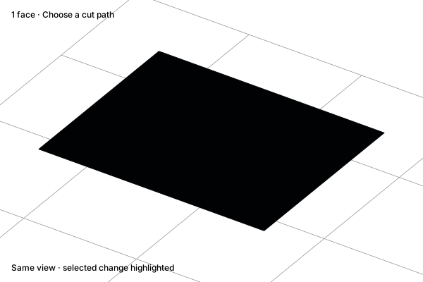
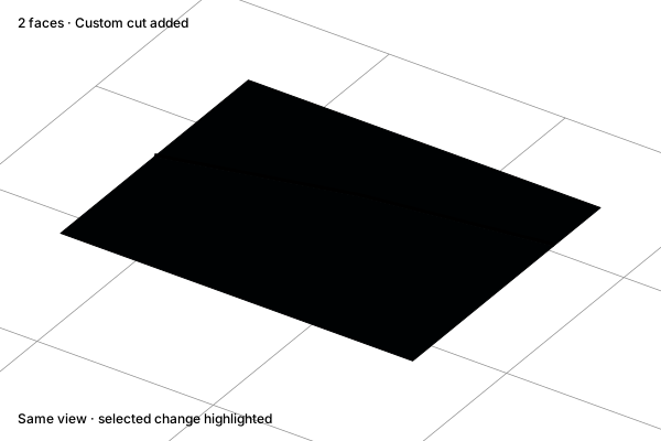
Knife cut

Place a deliberate cut across a face. New edges follow the chosen path, giving you control beyond a regular loop cut.

Before

Knife cut: An uncut surface

An uncut surface

After

Knife cut: A custom cut path

A custom cut path

Concept illustration. The diagrams explain the operation. Your result depends on the starting geometry and settings.
Before · SVGAfter · SVG
ReferenceExplore interactive example

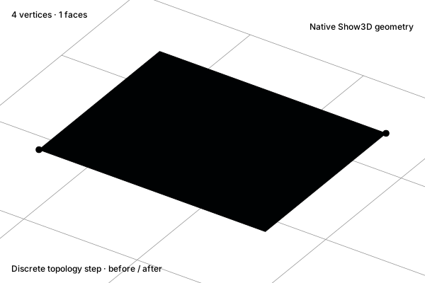
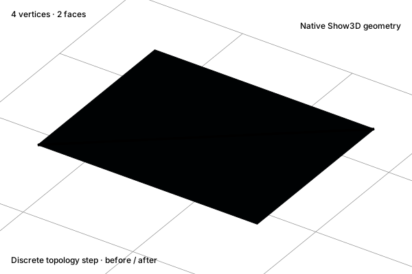
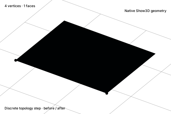
Connect vertices

Connect vertices across an existing face. The new edge divides that face without moving its vertices.

Before

Connect vertices: Two selected corners

Two selected corners

After

Connect vertices: A connecting edge

A connecting edge

Concept illustration. The diagrams explain the operation. Your result depends on the starting geometry and settings.
Before · SVGAfter · SVG
ReferenceExplore interactive example

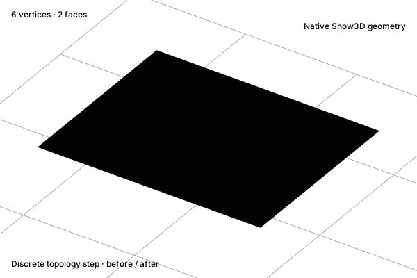
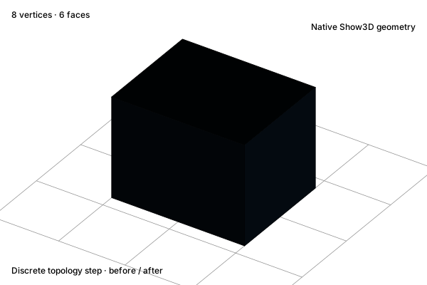
Subdivide a mesh

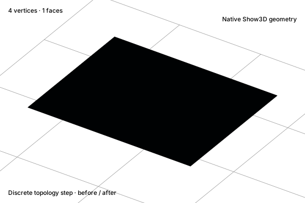
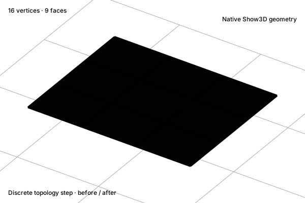
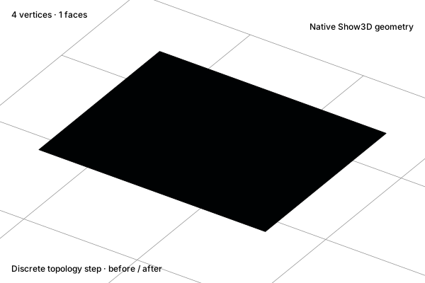
Split the selected surface into smaller faces. This edit adds topology without the smoothing of a Subdivision Surface modifier.

Before

Subdivide a mesh: One quad

One quad

After

Subdivide a mesh: A denser quad grid

A denser quad grid

Concept illustration. The diagrams explain the operation. Your result depends on the starting geometry and settings.
Before · SVGAfter · SVG
ReferenceExplore interactive example

Triangulate

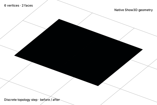
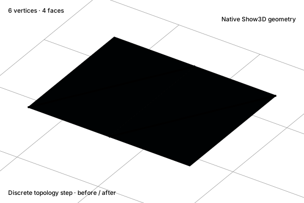
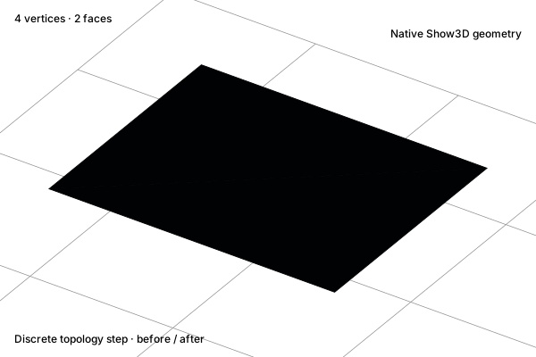
Divide polygon faces into triangles. The surface and outer boundary remain in place.

Before

Triangulate: Two quads

Two quads

After

Triangulate: Four triangles

Four triangles

Concept illustration. The diagrams explain the operation. Your result depends on the starting geometry and settings.
Before · SVGAfter · SVG
ReferenceExplore interactive example

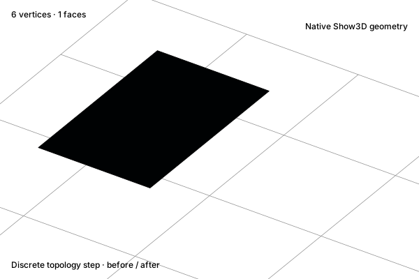
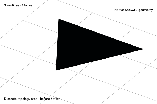
Triangles to quads

Merge a suitable adjacent triangle pair into a quad. Matching topology and surface conditions determine which pairs can be combined.

Before

Triangles to quads: A triangle pair

A triangle pair

After

Triangles to quads: One quad

One quad

Concept illustration. The diagrams explain the operation. Your result depends on the starting geometry and settings.
Before · SVGAfter · SVG
ReferenceExplore interactive example

Connect & repair

Bridge loops

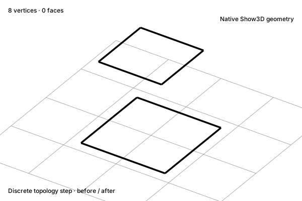
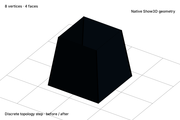
Build faces between compatible boundary loops. The example joins two four-edge loops into a continuous side wall.

Before

Bridge loops: Two open loops

Two open loops

After

Bridge loops: Connecting side faces

Connecting side faces

Concept illustration. The diagrams explain the operation. Your result depends on the starting geometry and settings.
Before · SVGAfter · SVG
ReferenceExplore interactive example

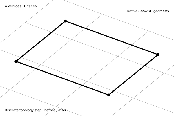
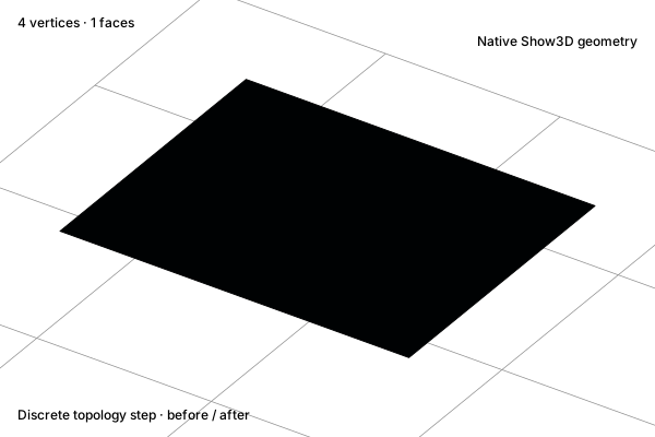
Fill a boundary

Create a face from a closed boundary. The boundary vertices stay fixed; the opening gains a surface.

Before

Fill a boundary: An open boundary

An open boundary

After

Fill a boundary: A filled face

A filled face

Concept illustration. The diagrams explain the operation. Your result depends on the starting geometry and settings.
Before · SVGAfter · SVG
ReferenceExplore interactive example

Delete faces

Remove the selected face and expose an opening. The context determines whether associated edges or vertices are also removed.

Before

Delete faces: A selected surface patch

A selected surface patch

After

Delete faces: An opening

An opening

Concept illustration. The diagrams explain the operation. Your result depends on the starting geometry and settings.
Before · SVGAfter · SVG
ReferenceExplore interactive example

Dissolve an edge

Remove an internal edge while preserving the surface. This example merges a flat face pair instead of leaving a hole.

Before

Dissolve an edge: Two coplanar faces

Two coplanar faces

After

Dissolve an edge: One continuous face

One continuous face

Concept illustration. The diagrams explain the operation. Your result depends on the starting geometry and settings.
Before · SVGAfter · SVG
ReferenceExplore interactive example

Merge at center

Weld selected vertices at their center. Connected faces adjust to the new shared vertex.

Before

Merge at center: Two selected vertices

Two selected vertices

After

Merge at center: One shared vertex

One shared vertex

Concept illustration. The diagrams explain the operation. Your result depends on the starting geometry and settings.
Before · SVGAfter · SVG
ReferenceExplore interactive example

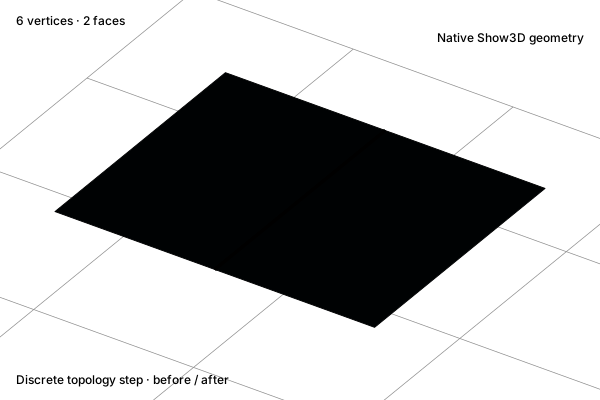
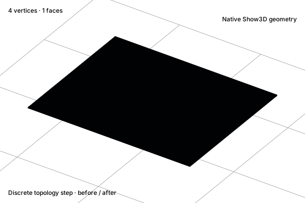
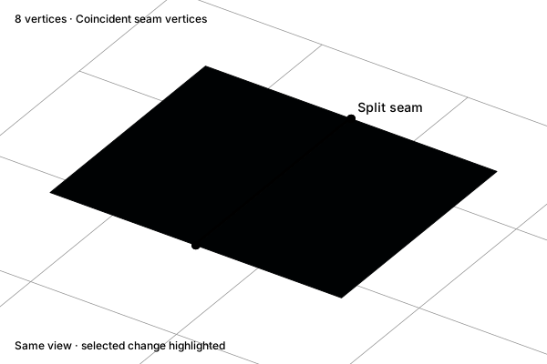
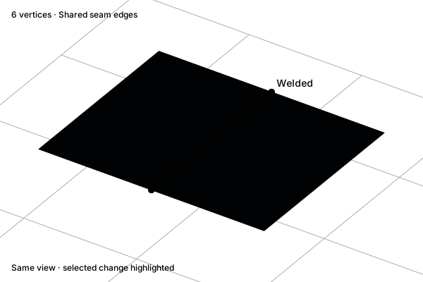
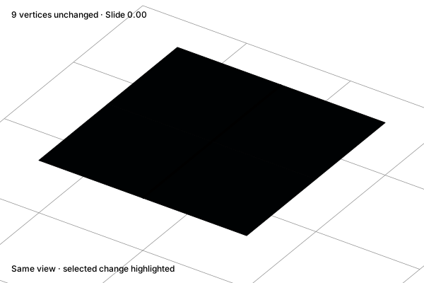
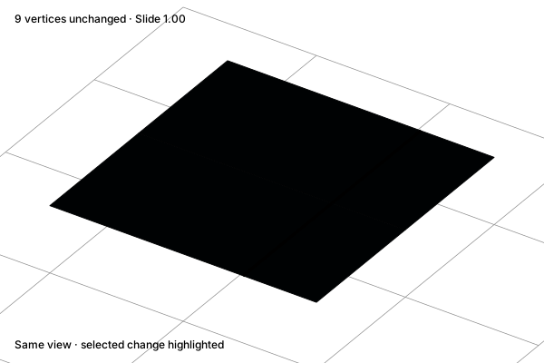
Merge by distance

Weld nearby vertices within a chosen tolerance. The example joins matching seam vertices without changing the outside boundary.

Before

Merge by distance: A split seam

A split seam

After

Merge by distance: A welded seam

A welded seam

Concept illustration. The diagrams explain the operation. Your result depends on the starting geometry and settings.
Before · SVGAfter · SVG
ReferenceExplore interactive example

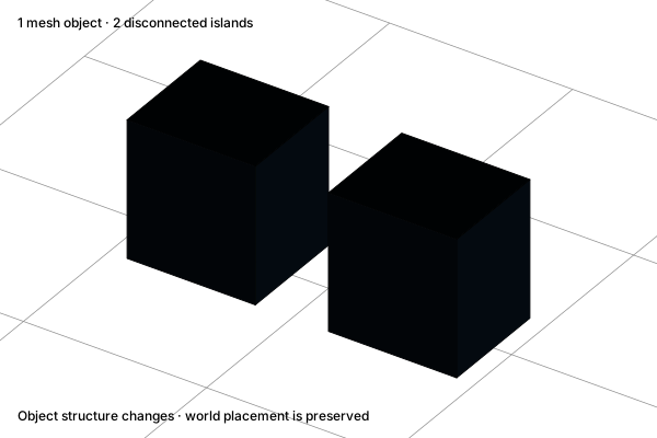
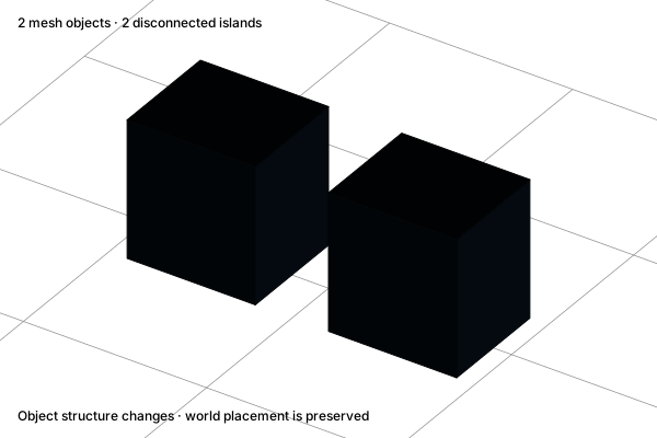
Separate geometry

Move selected geometry into its own object. The two pieces keep their world-space positions and become independently addressable.

Before

Separate geometry: One mesh, two islands

One mesh, two islands

After

Separate geometry: Two mesh objects

Two mesh objects

Concept illustration. The diagrams explain the operation. Your result depends on the starting geometry and settings.
Before · SVGAfter · SVG
ReferenceExplore interactive example

Slide an edge

Move an edge along existing adjacent topology. The outer boundary stays fixed while the spacing of faces changes.

Before

Slide an edge: A centered control loop

A centered control loop

After

Slide an edge: The loop moved along its rails

The loop moved along its rails

Concept illustration. The diagrams explain the operation. Your result depends on the starting geometry and settings.
Before · SVGAfter · SVG
ReferenceExplore interactive example

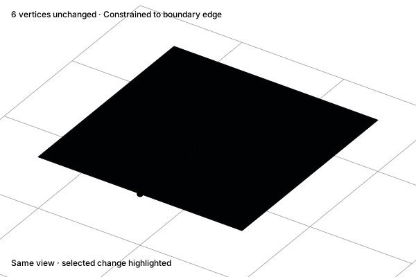
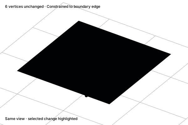
Slide a vertex

Move a selected vertex along an existing connected edge. This constrained edit differs from a free move.

Before

Slide a vertex: A vertex on an edge

A vertex on an edge

After

Slide a vertex: The vertex moved along the edge

The vertex moved along the edge

Concept illustration. The diagrams explain the operation. Your result depends on the starting geometry and settings.
Before · SVGAfter · SVG
ReferenceExplore interactive example

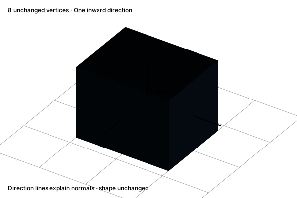
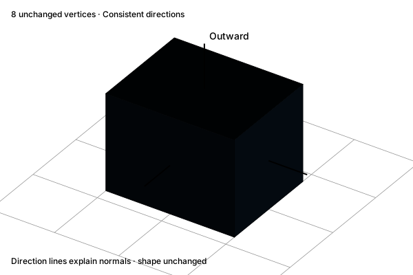
Recalculate normals

Correct the face directions used for surface orientation. The visible vertex positions stay unchanged.

Before

Recalculate normals: An inward face direction

An inward face direction

After

Recalculate normals: Consistent outward directions

Consistent outward directions

Concept illustration. The diagrams explain the operation. Your result depends on the starting geometry and settings.
Before · SVGAfter · SVG
ReferenceExplore interactive example

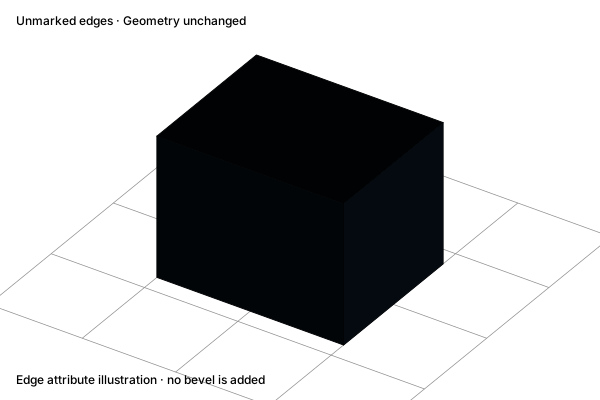
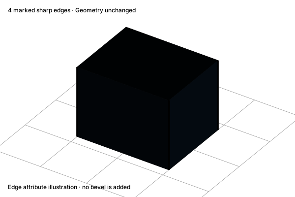
Mark sharp edges

Mark edges that should preserve a hard shading boundary. This changes edge attributes, not the silhouette or topology.

Before

Mark sharp edges: An unmarked edge boundary

An unmarked edge boundary

After

Mark sharp edges: A marked shading boundary

A marked shading boundary

Concept illustration. The diagrams explain the operation. Your result depends on the starting geometry and settings.
Before · SVGAfter · SVG
ReferenceExplore interactive example

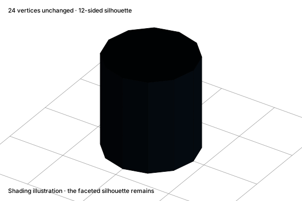
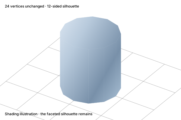
Smooth shading

Smooth the surface shading without adding vertices or rounding the silhouette. Use Subdivision Surface when the geometry itself needs smoothing.

Before

Smooth shading: Flat face shading

Flat face shading

After

Smooth shading: Interpolated shading

Interpolated shading

Concept illustration. The diagrams explain the operation. Your result depends on the starting geometry and settings.
Before · SVGAfter · SVG
ReferenceExplore interactive example

Modifiers & solids

Mirror

Reflect one side across the center plane. Edit the source half to develop a symmetric form; applying the modifier commits the evaluated result.

Before

Mirror: One half

One half

After

Mirror: Reflected across the plane

Reflected across the plane

Concept illustration. The diagrams explain the operation. Your result depends on the starting geometry and settings.
Before · SVGAfter · SVG
ReferenceExplore interactive example

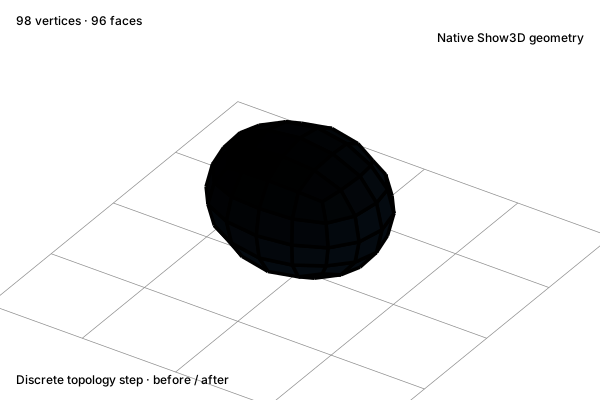
Subdivision Surface

Evaluate a denser, smoothed surface from the control cage. Unlike mesh Subdivide or Smooth Shading, this changes the evaluated geometry and silhouette.

Before

Subdivision Surface: A low-resolution control cage

A low-resolution control cage

After

Subdivision Surface: A smoothed surface

A smoothed surface

Concept illustration. The diagrams explain the operation. Your result depends on the starting geometry and settings.
Before · SVGAfter · SVG
ReferenceExplore interactive example

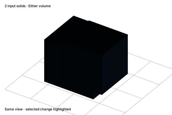
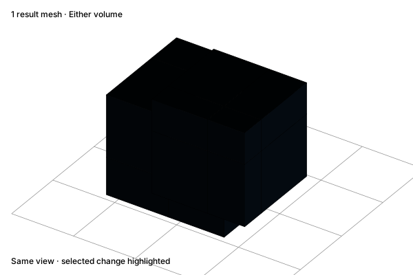
Boolean union

Combine the volume occupied by either solid and remove interior surfaces. This differs from grouping or joining object records.

Before

Boolean union: Two overlapping solids

Two overlapping solids

After

Boolean union: One combined volume

One combined volume

Concept illustration. The diagrams explain the operation. Your result depends on the starting geometry and settings.
Before · SVGAfter · SVG
ReferenceExplore interactive example

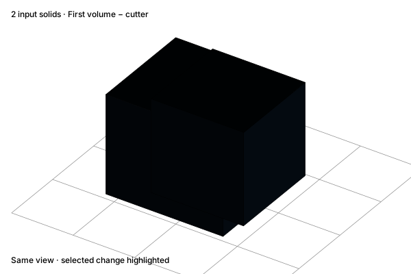
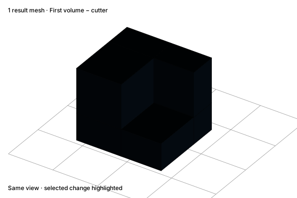
Boolean difference

Subtract the overlapping cutter volume from the first solid. The example produces a visible notch with new interior walls.

Before

Boolean difference: A solid and a cutter

A solid and a cutter

After

Boolean difference: The cutter volume removed

The cutter volume removed

Concept illustration. The diagrams explain the operation. Your result depends on the starting geometry and settings.
Before · SVGAfter · SVG
ReferenceExplore interactive example

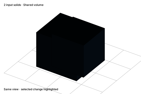
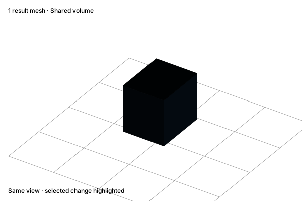
Boolean intersection

Keep only the space occupied by both input solids. Their non-overlapping portions are removed.

Before

Boolean intersection: Two overlapping solids

Two overlapping solids

After

Boolean intersection: Only the shared volume

Only the shared volume

Concept illustration. The diagrams explain the operation. Your result depends on the starting geometry and settings.
Before · SVGAfter · SVG
ReferenceExplore interactive example

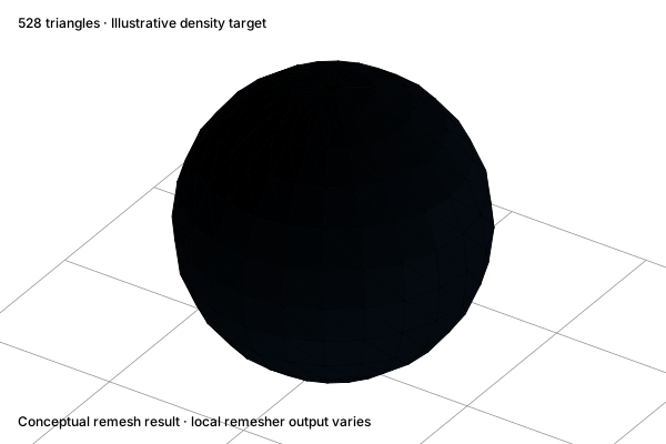
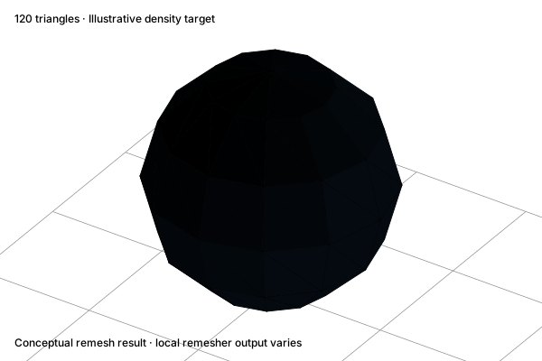
Remesh

Rebuild the surface with a different mesh density. The illustration shows an approximate shape-preserving target, not a guarantee of automatic production topology.

Before

Remesh: A dense triangle surface

A dense triangle surface

After

Remesh: A coarser triangle surface

A coarser triangle surface

Concept illustration. The diagrams explain the operation. Your result depends on the starting geometry and settings.
Before · SVGAfter · SVG
ReferenceExplore interactive example

Curves & profiles

Edit curve points

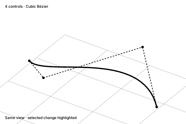
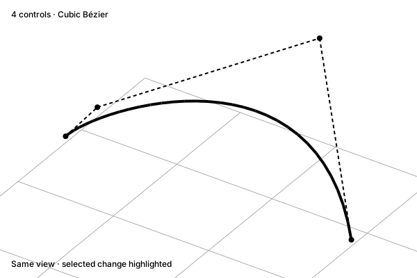
Move curve control points to adjust a path. A small change to its controls shapes the smooth curve between them.

Before

Edit curve points: Original control shape

Original control shape

After

Edit curve points: A revised curve

A revised curve

Concept illustration. The diagrams explain the operation. Your result depends on the starting geometry and settings.
Before · SVGAfter · SVG
ReferenceExplore interactive example

Extend a curve

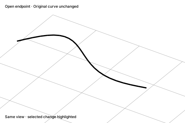
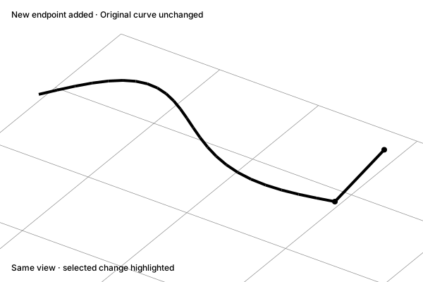
Extrude an endpoint to continue the curve. The original path remains, with a new control point and segment at its end.

Before

Extend a curve: An open endpoint

An open endpoint

After

Extend a curve: A new connected segment

A new connected segment

Concept illustration. The diagrams explain the operation. Your result depends on the starting geometry and settings.
Before · SVGAfter · SVG
ReferenceExplore interactive example

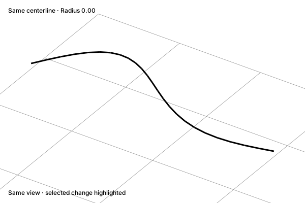
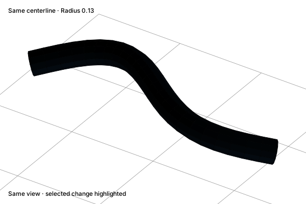
Give a curve thickness

Sweep a round cross-section along a path. The centerline remains the guide for the resulting volume.

Before

Give a curve thickness: A centerline path

A centerline path

After

Give a curve thickness: A tube along the path

A tube along the path

Concept illustration. The diagrams explain the operation. Your result depends on the starting geometry and settings.
Before · SVGAfter · SVG
ReferenceExplore interactive example

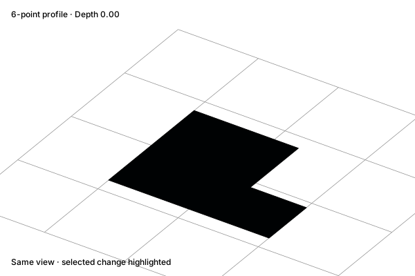
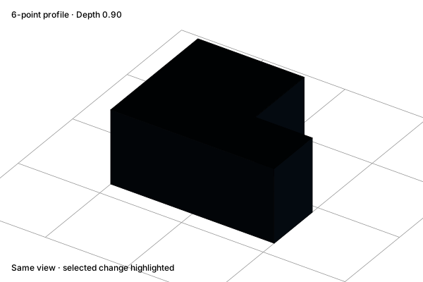
Extrude a profile

Extend a closed two-dimensional profile through a depth. The side walls follow the outline and caps close its ends.

Before

Extrude a profile: A flat profile

A flat profile

After

Extrude a profile: A solid profile extrusion

A solid profile extrusion

Concept illustration. The diagrams explain the operation. Your result depends on the starting geometry and settings.
Before · SVGAfter · SVG
ReferenceExplore interactive example

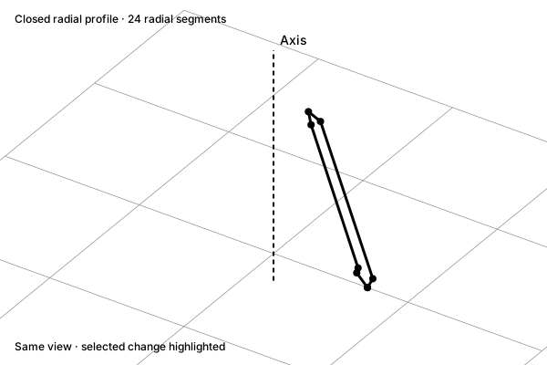
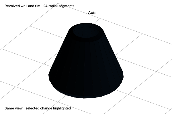
Revolve a profile

Revolve a profile around an axis to make a rotational form. The chosen profile includes wall thickness and a rim.

Before

Revolve a profile: A radial cross-section

A radial cross-section

After

Revolve a profile: A hollow revolved form

A hollow revolved form

Concept illustration. The diagrams explain the operation. Your result depends on the starting geometry and settings.
Before · SVGAfter · SVG
ReferenceExplore interactive example

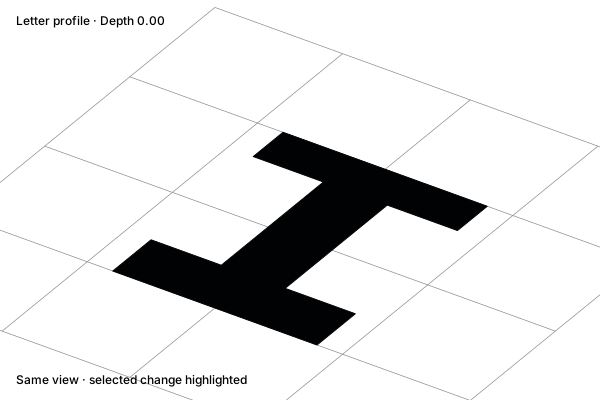
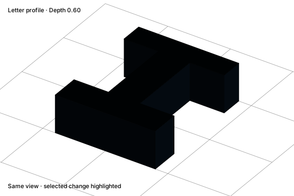
Extrude 3D text

Turn a letter profile into a dimensional object. Show3D exposes text content, font, size, depth, and bevel parameters.

Before

Extrude 3D text: A flat letter outline

A flat letter outline

After

Extrude 3D text: A letter with depth

A letter with depth

Concept illustration. The diagrams explain the operation. Your result depends on the starting geometry and settings.
Before · SVGAfter · SVG
ReferenceExplore interactive example

Sculpt & surface

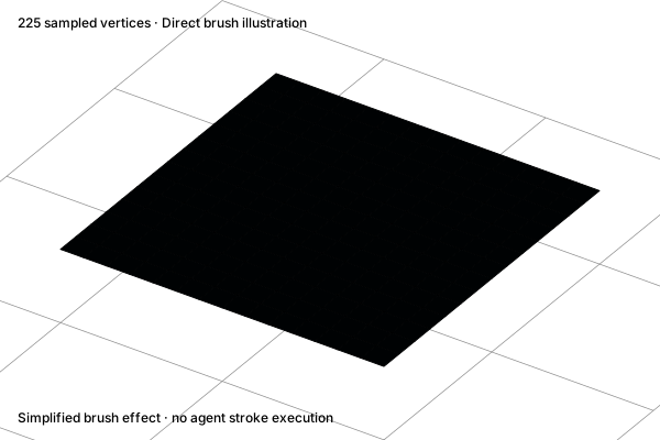
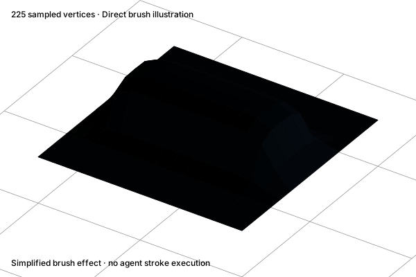
Sculpt with clay

Build up or remove surface volume with a brush stroke. This simplified height-field example shows a clay-like raised strip.

Before

Sculpt with clay: A flat sampled surface

A flat sampled surface

After

Sculpt with clay: A raised brush stroke

A raised brush stroke

Concept illustration. The diagrams explain the operation. Your result depends on the starting geometry and settings.
Before · SVGAfter · SVG
ReferenceExplore interactive example

Sculpt along normals

Displace the brush region along its sampled surface normal. The surrounding region stays fixed.

Before

Sculpt along normals: Original surface

Original surface

After

Sculpt along normals: A locally inflated surface

A locally inflated surface

Concept illustration. The diagrams explain the operation. Your result depends on the starting geometry and settings.
Before · SVGAfter · SVG
ReferenceExplore interactive example

Flatten a surface

Move the brush region toward a plane. The illustrated stroke flattens the top of a bump while preserving the outside patch.

Before

Flatten a surface: A rounded bump

A rounded bump

After

Flatten a surface: A flattened local patch

A flattened local patch

Concept illustration. The diagrams explain the operation. Your result depends on the starting geometry and settings.
Before · SVGAfter · SVG
ReferenceExplore interactive example

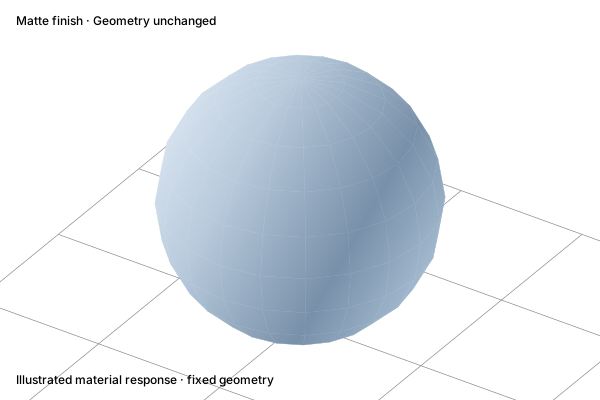
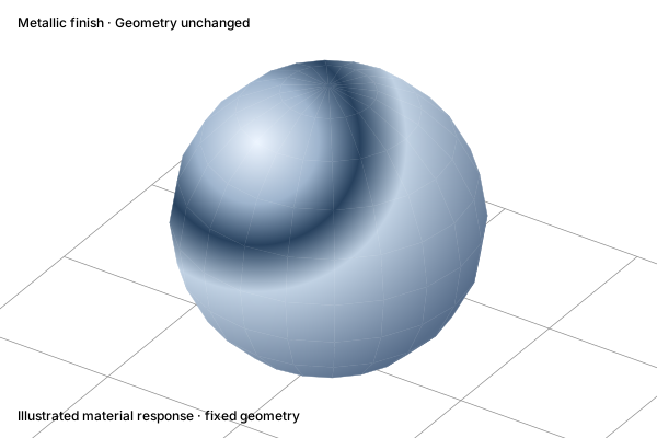
Change a material

Adjust the surface response using material properties. The geometry stays the same; the illustrated highlight only explains the finish change.

Before

Change a material: A matte surface

A matte surface

After

Change a material: A metallic surface

A metallic surface

Concept illustration. The diagrams explain the operation. Your result depends on the starting geometry and settings.
Before · SVGAfter · SVG
ReferenceExplore interactive example

Assign a face material

Assign a material slot to selected faces. Other faces keep their existing assignment.

Before

Assign a face material: One shared surface

One shared surface

After

Assign a face material: A different finish on one face

A different finish on one face

Concept illustration. The diagrams explain the operation. Your result depends on the starting geometry and settings.
Before · SVGAfter · SVG
ReferenceExplore interactive example

Adjust texture mapping

Change how an existing texture is repeated and oriented on the surface. This example explains mapping; it does not unwrap a mesh or load a new texture.

Before

Adjust texture mapping: Original texture scale

Original texture scale

After

Adjust texture mapping: A repeated texture

A repeated texture

Concept illustration. The diagrams explain the operation. Your result depends on the starting geometry and settings.
Before · SVGAfter · SVG
ReferenceExplore interactive example

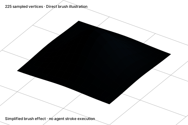
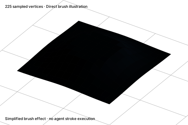
Paint a surface

Apply color to the surface with a direct brush stroke. Geometry stays fixed; Codex’s settings action does not paint the stroke for you.

Before

Paint a surface: An unpainted surface

An unpainted surface

After

Paint a surface: A painted stroke

A painted stroke

Concept illustration. The diagrams explain the operation. Your result depends on the starting geometry and settings.
Before · SVGAfter · SVG
ReferenceExplore interactive example