
Skip to content
Show3D
  • Community
  • Pricing
Search scenes
Create
OverviewDocumentationTutorials & coursesSearch Learn
  • Overview
  • Get started with Show3D
  • Modeling tools
    • Modeling examples
  • Materials & textures
  • Agent modeling
    • Connect Codex
  • Asset generation

In this topic

  • Extrude
  • Bevel
  • Select components
  • Select a loop
  • Extrude a vertex
  • Extrude an edge
  • Inset a region
  • Inset individual faces
  • Bevel a vertex
  • Loop cut
  • Knife cut
  • Connect vertices
  • Subdivide a mesh
  • Triangulate
  • Triangles to quads
Browse documentation
  • Overview
  • Get started with Show3D
  • Modeling tools
    • Modeling examples
  • Materials & textures
  • Agent modeling
    • Connect Codex
  • Asset generation

In this topic

  • Extrude
  • Bevel
  • Select components
  • Select a loop
  • Extrude a vertex
  • Extrude an edge
  • Inset a region
  • Inset individual faces
  • Bevel a vertex
  • Loop cut
  • Knife cut
  • Connect vertices
  • Subdivide a mesh
  • Triangulate
  • Triangles to quads

Learn

Learn overviewDocumentationTutorials & coursesConnect Codex
XiaohongshuDouyinBilibili

Copyright © 2023 - 2026 Show3D Technology Limited. All rights reserved.

Terms of UsePrivacy Policy
Modeling tools
  1. Learn
  2. Documentation
  3. Modeling tools
  4. Select components

Select components

Choose vertices, edges, or faces to focus an edit. Selection alone changes no geometry.

Before you start

Select the mesh objects to edit. Each selected object must support mesh editing and be visible. Hidden objects, unsupported objects, and selections sharing the same geometry can prevent entering a combined edit session.

Use the operation

Limit a geometry change to the intended vertices, edges, or faces.

  1. Open Mesh Edit and choose Enter Edit Mode. The modeling workspace also supports Tab to enter or exit.
  2. Choose Vertex Select, Edge Select, or Face Select. The toolbar displays 1, 2, and 3 for these modes.
  3. Select the components and inspect the highlighted region. Use Select Through only when hidden components should participate.
  4. Perform the geometry operation, inspect its result, and exit edit mode when returning to object-level work.

Controls and choices

ControlsWhat changes
Selection modeChanges the component type addressed by subsequent commands and context menus.
Select ThroughAllows selection through visible surfaces. Orbit the view before editing a selection made through the mesh.
Selected objectsDefines the meshes participating in the edit session. Object operations belong outside the session.

See what changes

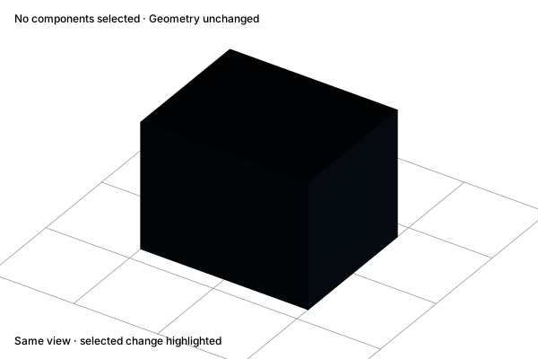
Before

Select components: The whole mesh

The whole mesh

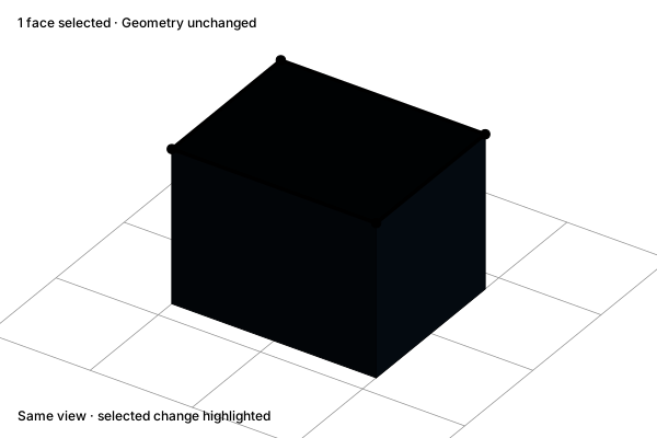
After

Select components: A selected face and boundary

A selected face and boundary

Concept illustration. The diagrams explain the operation. Your result depends on the starting geometry and settings.

Check the result

Selection should not change the mesh by itself. If a command is unavailable, check its required component type and the current selection before adding geometry. Avoid treating all highlighted components as one connected region when several meshes are being edited.

Related operations

Select a loopExtrudeAlign verticesDelete faces

Practice in Show3D

Open the editor and follow the steps with your own scene.
Start modelingModeling essentials

On this page

Before you startUse the operationControls and choicesSee what changesCheck the resultRelated operations